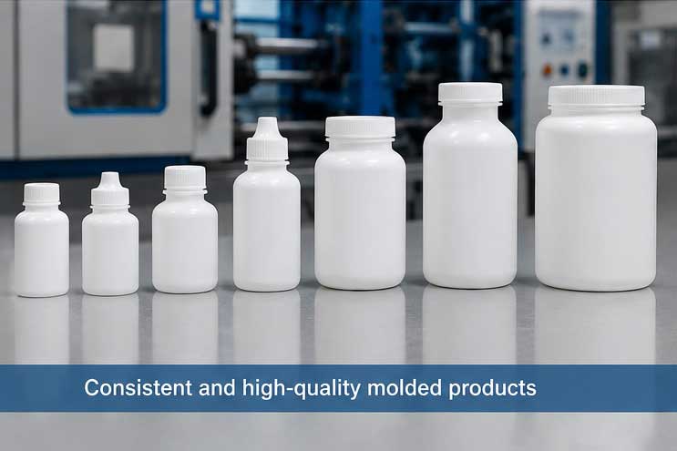
Injection Blow Molding (IBM) stands as a cornerstone technology for manufacturing high-precision hollow plastic products, from pharmaceutical bottles and cosmetic containers to industrial packaging. The mold—the heart of the IBM process—demands rigorous engineering, precise fabrication, and systematic validation to transform a product concept into consistent mass production. This article outlines the end-to-end IBM mold development workflow, grounded in real-world manufacturing applications, focusing on mechanical design, material science, process validation, and quality control.
The journey begins with Requirement Definition & Design for Manufacturability (DFM) Analysis, the foundation of successful mold development. The project team collaborates closely with clients to crystallize all technical specifications: product geometry (including neck finish, wall thickness, and undercuts), material type (PE, PP, PET, or other thermoplastics), production volume, dimensional tolerances (typically ±0.05–0.1 mm for critical features), and surface finish (smooth, textured, or embossed).
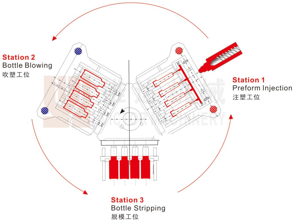
Next, engineers conduct a thorough DFM review tailored to IBM’s unique three-station mechanism (injection, blowing, ejection). Key checks include:
Preform feasibility: Ensuring the preform shape can support uniform blowing without thin spots or distortion.
Draft angles: Verifying sufficient draft (1°–3°) for clean demolding from core pins and blow cavities.
Wall uniformity: Balancing thickness to avoid uneven inflation and ensure structural integrity.
Neck precision: Confirming the critical neck thread and sealing surface can be accurately molded and maintained.
This phase concludes with a formal feasibility report and approved 3D product model, freezing design changes to prevent costly mid-process iterations.
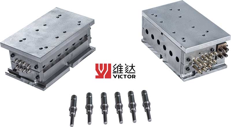
With the product finalized, the team advances to Mold Concept & Structural Design. IBM molds are far more complex than standard injection molds, as they integrate two distinct cavities (preform and blow) and interface with rotating core pins on a multi-station machine.
Engineers first define the mold layout:
Cavitation: Determining single or multi-cavity design (4–32 cavities common for high-volume IBM) based on output demand.
Core & cavity layout: Aligning preform and blow cavities to match the machine’s indexing rotation.
Key systems: Designing the injection gate (usually pinpoint or hot runner), cooling circuits (for uniform heat extraction), venting (to eliminate air traps), and ejection/stripping mechanisms.
For materials, high-performance tool steels are selected: S136 or 420 stainless steel for corrosion and wear resistance (ideal for PE/PP), and H13 for high-temperature PET processing. Core pins require precise hardness (HRC 50–54) and surface polishing (Ra ≤ 0.2 μm) to ensure smooth preform release and consistent wall thickness. The design is finalized via CAD modeling and internal design review, with a focus on durability, maintainability, and alignment with IBM machine specifications.
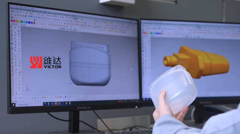
Detailed Engineering & CAE (Computer-Aided Engineering) Validation refines the design and de-risks production. Engineers generate 2D manufacturing drawings for every component, specifying tolerances, surface finishes, heat treatment, and assembly requirements. A complete BOM (Bill of Materials) is created for standard and custom parts.
Critical to this phase is mold flow simulation (e.g., Moldflow) to analyze:
Preform injection: Melt flow patterns, pressure distribution, and cooling rates to avoid weld lines or incomplete filling.
Blow inflation: Air distribution and wall thickness distribution during the blow stage, ensuring uniformity across the container.
Thermal performance: Cooling circuit efficiency to maintain consistent cycle times and part stability.
Simulations identify potential flaws—such as uneven wall thinning or overheating—allowing design adjustments before fabrication. This digital validation drastically reduces physical prototyping costs and shortens development cycles.
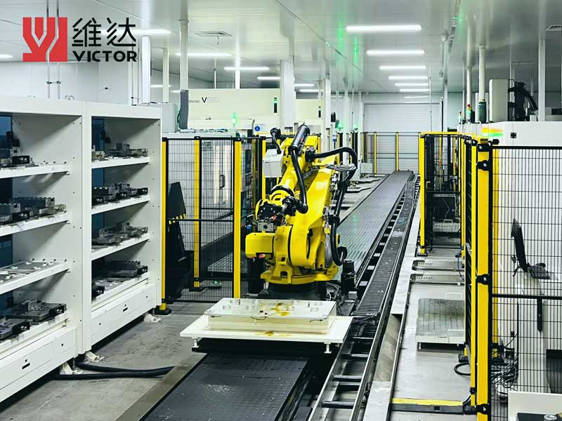
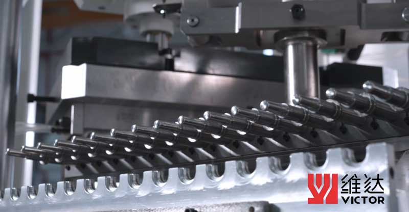
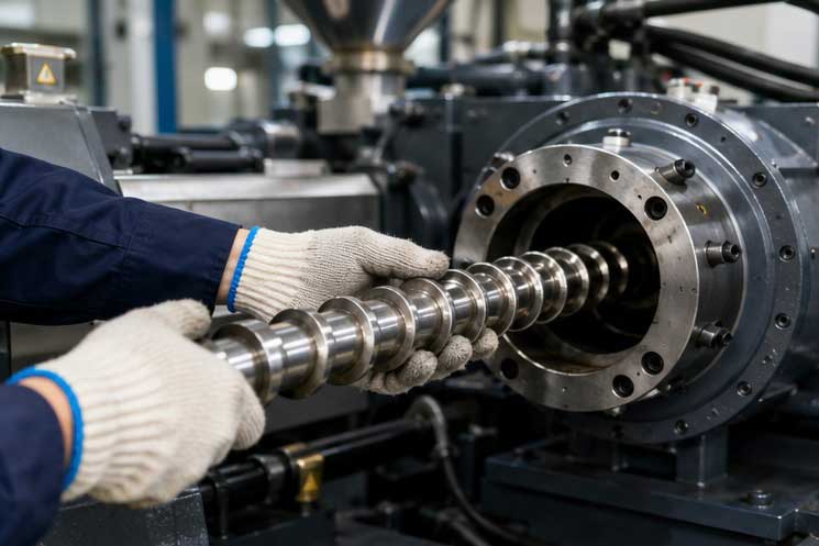
The approved design moves to Precision Fabrication & Assembly, where digital models become physical tooling. The process follows strict CNC machining protocols:
1.Rough machining: Cutting mold blocks, cores, and cavities from solid steel billets.
2.Semi-finishing & heat treatment: Machining to near-net shape, then hardening via quenching and tempering to achieve target hardness.
3.Finishing: High-speed CNC milling, EDM (electrical discharge machining) for complex contours, and grinding for critical surfaces.
4.Polishing: Manual and automated polishing to achieve mirror finishes (Ra ≤ 0.1 μm) for transparent containers.
Skilled toolmakers then assemble the mold, integrating the preform and blow sections, cooling lines, guide pins, ejectors, and hot runner systems (if used). Precision alignment is critical: core pins and cavities must align within ±0.01 mm to avoid flash, offset walls, or defective parts. A full mechanical check verifies smooth opening/closing and proper function of all moving components.
Mold Testing, Sampling & Debugging is where the mold proves its viability. The completed tool is installed on a dedicated IBM press (e.g., Jomar or Uniloy machines) for initial sampling. Engineers run incremental trials, adjusting process parameters:
Injection: Temperature, pressure, speed, and hold time to form defect-free preforms.
Transfer: Indexing speed and positioning to prevent preform deformation.
Blowing: Air pressure (3–8 bar), flow rate, and blow time to achieve full cavity replication.
Cooling: Cycle time and water flow to ensure solidification before ejection.
Samples are inspected for dimensional accuracy (via CMM), wall thickness (ultrasonic gauge), visual defects (flash, haze, scratches), and functional performance (leak testing, thread fit). Any issues—such as uneven walls, poor neck sealing, or sticking parts—trigger root-cause analysis and targeted mold modifications: polishing, welding, machining, or cooling adjustments. This iterative cycle continues until the mold produces consistent, compliant samples.
Before full production, Process Validation & Production Part Approval Process (PPAP) ensures long-term stability. Three validation runs (at minimum) are conducted under simulated mass-production conditions, with continuous monitoring of key metrics:
Dimensional repeatability: All critical dimensions must meet tolerance; CPK ≥ 1.33 for critical features.
Process capability: SPC (Statistical Process Control) tracks weight, wall thickness, and cycle time consistency.
Reliability: Extended runs (8–16 hours) test for wear, cooling efficiency, and maintenance requirements.
Upon passing validation, a full PPAP package is compiled—including dimensional reports, material certifications, FMEA, and control plans—securing formal customer approval. The mold is then cleaned, tagged, and prepared for handover to production.
The final stage is Mass Production & Continuous Improvement. The validated mold enters full-scale manufacturing, with operators following standardized setup, maintenance, and inspection protocols. Routine checks include:
Daily: Cleaning, lubrication, and sample quality audits.
Weekly: Wear inspection of core pins, cavities, and moving parts.
Periodic: Cooling circuit pressure testing (8 bar, 15+ minutes) to prevent leaks.
Over time, production data drives incremental improvements: minor geometry tweaks for better yield, material upgrades for extended mold life, or process optimizations for faster cycles. This closed-loop system ensures the mold delivers consistent quality across its entire lifecycle (typically 1–5 million cycles for high-volume IBM molds).
The IBM mold development process is a disciplined, multi-stage journey that merges engineering expertise, precision manufacturing, and rigorous validation. By systematically advancing from requirement analysis to mass production—with constant focus on DFM, simulation, testing, and improvement—manufacturers ensure their IBM molds deliver the precision, efficiency, and reliability demanded by pharmaceutical, cosmetic, and packaging industries. In an era where quality and consistency are non-negotiable, a well-executed mold development process is not just a technical necessity but a critical competitive advantage.